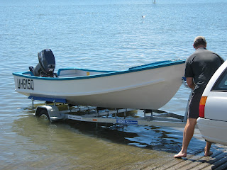
The Planing Hull/Displacement Hull Trailer Problem
Monohedron hulls, and the related type commonly know as a "warped-vee" sit well on a trailer which has longitudinal skids (or bunks), for lateral support and centreline rollers to support the keel. Because in most planing hulls the keel and buttock lines are parallel, or close to parallel, these stock trailers work well with the limited adjustment built into their roller and bunk mountings.
 |
| This is a Phil Bolger-designed Diablo built by Patrick Querengasser. You can see how the conventional trailer arrangement works very well with a monohedron hull such as this. |
 |
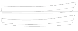
| Fleet (top) and Flint (bottom) compared in profile |
 |
| Note how the skeg allows the centreline rollers to run aft in a straight line. |
No Skeg, No Keel Batten, and Flat Bottom
But what happens if the designer of the boat does not incorporate an external keel or a skeg? A few years back I built a Jim Michalak-designed Mayfly 14 for a customer. I really like the Mayfly 14, but she does not have a skeg, does not have an external keel batten, and does have very marked rocker in the bottom.
 |
| Mayfly 14 - beautifully adapted to the water, but a real problem when it comes to trailer design. |
Because Mayfly 14 has a flat bottom, and no keel batten to engage in the normal "cotton reel" centreline rollers on a production trailer, a bit of lateral thinking was required.
 |
| Here is the sort of external keel batten I normally design. This one is still very rough, but you get the idea - just a tapered piece of 3/4" stock glued and screwed on the flat. |
To have a commercially-built, hot-dip galvanised trailer custom-made would have been far too expensive, so what I did was to select a suitably sized trailer frame from the manufacturer's standard line, and purchase it without any of the rollers and bunks fitted. I then padded the straight cross pieces with lengths of UHMW polyethylene (or at least that is what I think it is! At any rate, "slippery plastic") and placed an extra cross piece at the forward end supported by stock-standard adjustable forks.
 |
| Here is the boat loaded on the trailer, showing the adjustable, elevated forward cross-piece. |
The Bending Trailer Problem
The commercial trailer frames that we use for light-weight sailing, rowing, and motoring boats are built to a minimum standard in order that the manufacturers can compete effectively in the market. The box-section steel (RHS) used in the majority of these light trailers is quite springy, and the trailers are usually supported by a single axle. In most cases the light-weight trailers have a keel roller at the rear and front cross-pieces, and one on a cross-piece near the middle - which is normally in the same sort of longitudinal location as the trailer axle.
 |
| On this Periwinkle trailer you can see the three centreline keel rollers |
I have three approaches to solving this problem. Firstly, I try to tie down the boat using a single strapping arrangement (usually with a strongback incorporated) located fairly close to the longitudinal location of the axle and middle trailer roller. It doesn't have to be exact, but just in the general area. Secondly, I arrange things so that the bow and stern are free to move upwards a little under load.
Lastly, and far and away most importantly, I position the centreline rollers such that the middle one is below the level of the forward and aft rollers. This way, as the boat is winched onto the trailer, the bow rides up on the rear roller, moves forward onto the middle roller, and then finally rolls upwards onto the forward roller. So, the middle roller supports the boat as she comes forward on the trailer during retrieval, but as the boat is winched into the final location with the bow against the winch-post, the keel lifts clear of the middle roller. Ideally, the forward and rear rollers should be positioned under a frame or bulkhead so as to distribute loads throughout the hull.
The reason for the vertical location of the rollers which I have just described is to allow the trailer to bend upwards due to road shocks without the middle roller actually touching the hull, and tending to break the back of the hull.
A Better Trailer for Lightweight Boats of Traditional Design?
Currently I'm designing an experimental trailer to carry boats such as Phoenix III, First Mate, and Periwinkle. This trailer will incorporate transverse supports instead of the longitudinally positioned keel rollers of the standard commercially-built trailers. Remember how well this worked for the Mayfly 14 trailer problem?
There will be a total of three transverse supports, but the middle one will only support the boat during loading (refer to the previous few paragraphs), and when the boat is fully loaded on the the trailer, she will be supported vertically at only two places - both of which will coincide with frames or bulkheads in the boat.
The trailer design is not yet finalised, and I'll have a couple of different frame designs, depending on the frame material (they will not always be made of steel, nor even aluminium....). However, in order to illustrate the basic idea, I have included some rough sketches for your information and to aid visualisation.
The Catch
There always has to be a catch, and this case is no different. Unless you are lucky enough to find a commercial trailer frame which will adapt to the dimensions of your boat (as I did with Mayfly 14), you will have to pay a lot of money to have one built as a custom project, or you will have to build it yourself. Rules will be different in different places, but where I come from there are regulations and standards that have to be met before a home-made trailer can be registered for use - so do your homework. As you can see from what I wrote at the beginning of the article, for most boats a commercial product can be used as long as it is correctly adjusted. The single most important element as far as I'm concerned is making sure that the middle support or roller is not going to damage your boat due to road shocks.


Perhaps you might look at the Hartley trailer design which was provided with the Hartley TS boat plans, for some ideas for a more robust trailer frame which would not flex much when the trailer wheels hit bumps. Copies of his trailer design is published in the Hartley boatbuilding guides of the 1970s and 80s. Graeme Dennett
ReplyDeleteHi thanks for a great article! Your sketch is exactly what I'm looking for. Unfortunately I haven't been able to find anything like it in the US at least. What are your thoughts on the Trailex aluminum line? The main difference I see is that they are built around 1 long center support. Thanks, Andrew
ReplyDeleteThis article on Trailer Design for displacement smallcraft is a fascinating deep dive into a niche but critical aspect of boat transportation. As someone who's always been intrigued by the engineering behind these seemingly mundane components, I really appreciate your attention to detail and practical solutions. Your discussion of how to prevent the trailer from damaging the boat during transport due to road shocks is a crucial consideration that many might overlook. Your emphasis on proper support placement and the need to ensure that the middle roller doesn't harm the boat is a valuable insight for anyone involved in boat transportation.
ReplyDeleteThis article provides a comprehensive overview of trailer design considerations for displacement smallcraft. I appreciate how it covers both the technical aspects, such as axle placement and weight distribution, as well as practical tips like trailer maintenance and launching techniques. Understanding these nuances is crucial for ensuring the safe transport and longevity of small watercraft. Looking forward to more insights on optimizing trailer designs for different types of boats! Boat Trailer
ReplyDeleteHi Ross
ReplyDeleteI own a green island 18, the homemade trailer it’s sitting on has had its day. The trailer was based on the design supplied with the boat plans. The boat has always been a bit hard to locate on the keel rollers. I want a new trailer and am happy to adapt a stock trailer. I’m in Coffs Harbour and travel up to Brisbane quite a bit. Can you or anyone else recommend a supplier/builder who I could talk to re buying a new trailer?