Thursday, September 29, 2011

Design Evolutuion

Naval Architecture and small craft design as we know it today is a relatively new process in human terms. By that I mean the design of boats by the use of paper drawings and, more recently computer modelling. I do not know enough about the detail of the history to make any definitive statements without research, but broadly speaking I think that the last 300 years would just about cover the span of "paper" design.

Boatbuilding (and presumably design) in present day Vietnam. Photo courtesy Bill Bradley

Once again in general terms, small craft design lagged behind when it came to plans drawn on paper as the first step in producing a boat. Well into the twentieth centuary, and in fact right up until today, small boats have been designed and built by eye and intuition, coming together and evolving on the builder's strongback.

I've got plenty of boat designs in my own portfolio, but I've only published a few. When I say designs, what I really mean is that I have a large number of lines drawings and finished computer models (even some carved half-models, of which the current computer models are a modern equivalent). Although the modelling of a hull, calculation of the hydrodynamics, and the drawing of the lines represents a large part of the creative side of boat design, the really time-consuming part is the detailed drafting of the building plans. Much modern design software deals with the detailed structural drafting semi-automatically, but I do my drawing manually, line-by-line in a simple 2D CAD program. Effectively, it is simply drawing in a conventional manner, but using an electronic drawing board - at least it makes erasure much cleaner!

This photo shows me making the lines drawing of Phoenix III. These days I do it electronically. 
For a number of years now I have felt uncomfortable about the number of plans being pumped out around the world for commercial gain. I know that people are always after something just a bit different, but in years gone by, existing designs evolved to meet the requirements of the customer rather than the market being flooded with new designs just for the sake of having a new design. The result was that bad elements were designed out and good elements were improved upon, giving rise to boats which were better and better suited to their intended function. It is with that in mind that I have been holding back on publishing extra plans.

In the last couple of weeks, I have been approached by a customer who had bought a set of plans for my Phoenix III design, asking whether the boat could be built using the glued-strip plank method.

The very first Phoenix III on launching day. Photo Rhonda Lillistone
Now, I designed Phoenix III from the very outset to have five wide planks of plywood planking making use of the excellent glued-lapstrake building method. My idea was to make use of the cross-grain strength of marine plywood, and to capitalise on the width of the available material. Also, I was aware that many people are intimidated by the thought of making a large number of planks, so I felt that five wide planks would provide a good compromise between a rounded lapstrake hullform and ease of building. The resulting boat has been very sucessful, and I'm quite proud of the overall design.

Phoenix III has several different rig options - this is the balance lug, which sets on exactly the same mast as the sprit rig. Photo Paul Hernes

Because I designed Phoenix III for five wide planks per side, I drew the bulkheads and molds with a number of flats to take the individual planks. This makes it much easier for an inexperienced builder to determine the lay of the planks and makes spiling (the determination of the plank shape on the flat) much simpler. The problem is that it would not allow the customer to build the boat using the glued-strip-plank method. I was tempted to tell him to use a spline to simply draw a curve through the points of the flats on all of the sections, but I wasn't convinced that the resulting shape would be fair.

A half-section through the hull, showing how the wide planks lay against flats on the bulkheads and molds.
What I ended up doing was to import the existing hull shape into the DELFTship Professional which I currently use for hull modelling, and then altered the entire hull from one with five flats per side, to one with a fully rounded, smooth hull surface.

Phoenix III perspective

Phoenix III perspective

Phoenix III lines plan


I have since carried out a similar modification to my Periwinkle design, which was drawn in the same way as Phoenix III.

Periwinkle on launching day. Photo Paul Hernes
One of the side benefits of this process has been that I have been able to make variations to the hull shapes where thought beneficial. In the case of Phoenix III I left her exactly as designed with the exception of making the hull smoothly rounded. But for Periwinkle, I increased the height of the bow very slightly and filled out the sheer line forward in plan view a little. This was made possible because the smoothly rounded hull does not have to comply with the limitations of developable plank shapes, which is necessary with the five plank hullform.

So, here is an example of improving (hopefully) existing designs with small, incremental alterations carried out where experience indicates they may be beneficial.

Having said all of this, I encourage anybody who feels the urge to have a go at designing their own boat. Experience begins at the beginning!

Monday, September 19, 2011

Build a Model

The vast majority of my plans customers seem to be first-timers, and the building process - particularly visualisation - can be quite intimidating. Without any shadow of a doubt there are three primary aids in making a good start: -
  • reading the correct text books (be extremely cautious about internet forums);
  • spend plenty of time studying the plans;
  • build a scale model.
The first two are self-explanatory, and I provide a recommended reading list with my plans, and try to make the plans detailed, supported by a comprehensive set of instructions.

Phoenix III plans - 30 sheets of A3 drawings and 50 pages of illustrated instructions.
Making a scale model is relatively simple if you follow the plans of the full-szed boat. The model doesn't have to be a masterpiece, but should follow exactly the sequence of constrution as specified in the plans.

Sometimes I build an exact replica using scale thickness plywood and scale thickness lumber of the same density as the full-sized boat. This allows me to test trim, stability, flotation and other elements of the design. At other times, I model only a section of the boat to examine things such as panel developments and curvature.

Hull panels for my Three Brothers design cut from 1.5mm Hoop Pine marine plywood to produce a 1/8th scale model.
Scale stitch-and-glue process
Hull panel developments being tested.
Anticipated shape confirmed as being developable
Sometimes people find it difficult to locate scale thickness plywood, but using balsa or other timber can still produce a worthwhile model for shape visualisation, and to help one understand the construction process.

Dan Taylor's model of Phoenix III
Another photo of Dan Taylor's Phoenix III
My good friend Doug Laver is building a model of First Mate just for the fun of it. He intends sailing the boat using radio control, and has replaced the centreboard with a ballasted fin keel to make up for the lack of crew weight out on the gunwale.

Dougs First Mate parts cut at 1/5th scale using plywood
Lots of little clamps in use
Ballast keel inserted in centreboard case from below
First Mate waiting for her lead ballast and her rig
Modelling may appear to be a time-consuming business, but in the long run it usually saves time - and it is fun!

Saturday, September 10, 2011

Thoughts on V-Bottomed Hulls

There is a lot of prejudice about flat-bottomed hulls, even though ones of good design can make excellent boats. But in western culture there is a far greater acceptance of the V-bottomed hull-form. I guess it is just a case of what we are used to seeing - westerners are familiar with the V-bottomed form and see it as being quite normal, just as I imagine that Chinese and South-East Asian people would have little argument with the virtues of a flat-bottomed boat.

Flint showing her V-bottomed hull-form
More than anything, I believe that concerns about pounding prevent the wider acceptance of flat-bottomed hulls.

A good example of a flat-bottomed sailing hull - this one is a Green Island 15
Any light-weight boat will pound, but if well heeled over, a flat-bottomed hull will run softly because the sharp angle between the bottom and the topsides acts as a "V". But if the boat is upright pounding can be a real problem.

I've designed a number of V-bottomed hulls, but my main reason for using this form has been to gain stiffness in the bottom panels. The V-bottom picks up stiffness because the bottom is broken into two halves, and the keel line is very stiff indeed due to the convexity of the bottom in two directions - somewhat similar to the strength in an eggshell, which would break easily if a flat panel, but is extremely strong for its weight when in a compound, convex shape.

That is me sanding the keel line of Flint. You can easily imagine how stiff the bottom is, even though it is made from 6mm (1/4") plywood. If it was a flat panel it would be very flexible if not supported by internal framing.
My primary concern with hard-chined hulls, regardless of whether they are flat-bottomed, V-bottomed, or multi-chined, is the matter of turbulence where the flow of water crosses the chine line. Without access to tank-testing or sophisticated Computational Fluid Dynamics (CFD) programs, my assessment of correct hull design for hard-chined forms has been based on intuition and common sense backed-up by insights I've gained from the writings of the late Philip C. Bolger.

One method of reducing turbulence around the chine is to keep the chine out of the water altogether - both Jim Michalak and Phil Bolger have used this technique a number of times - but the problem with that is it generally works well only if the boat is a light displacement design intended to run on an even keel e.g. rowing boats and power boats.

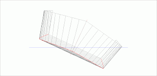
When more displacement is required, I use a different approach. A good example for discussion is my Alby design, which is a short pram dinghy designed to be short, but able to carry a heavy load. She was designed for my friend, Allan Burke. In order to maximise the displacement (therefore increase the carrying capacity), I used a lot of keel rocker, and reduced the angle of the "V" in the bottom amidships to only about 3.5 degrees. However, in order to reduce pounding, I twisted the bottom panels to give a relatively sharp "V" at the waterline foreward and aft - 18 to 20 degrees of deadrise.


In the drawing above, you can see how the chine-line (drawn in red) sweeps down strongly from the bow and stern to the lowest point amidships. The resulting hull is almost flat-bottomed amidships but quite well V'd at the bow and stern. I could have made her totally flat in the middle, but I left enough "V" to give the "eggshell" stiffness of a convex shape.

Some people will tell you that running a chine deeply into the water will cause excess turbulence and drag, but that is only the case if the hull is incorrectly shaped in 3D. You must consider a boat shape in profile, plan and body plan (i.e. end elevation) to get some idea of how the water will flow.


Above you can see the same hull viewed in body-plan . See how the designed curve in the topside panels and the bottom panels has resulted in a clean and well-streamlined chine-line (drawn in red)?


Now look at the same hull heeled at 20 degrees. The chine-line is forming a beautiful "V" with very little to cause turbulence, or to hold the boat back. This is one of the primary reasons why a well-designed pram or scow can be so fast - particularly in flat water.

This may give a clearer idea of how well the shape will slip along with minimal turbulence.
The only way to achieve the same effect on a sharp-bowed boat is to run the chine very high at the bow. An excellent example of this approach is Jack Holt's Mirror 16 design.

Mirror 16 showing chine-line. (courtesy Terence, Boatdesign.net)
In contrast, have a look at a hull with a hard chine and the chine-line left low at the bow - you can imagine how much turbulence and resistance would be generated by the chine (drawn in red) being forced forward through the water.


These are just my own thoughts, but I'm sticking with them at this stage.