Tuesday, December 31, 2013

Sprit Rig Virtues and Details

Of my published designs, two of the most popular (Phoenix III and First Mate) make use of a sprit rig with a small jib set flying. You can read some of my comments about the rig in this post from May 2012.

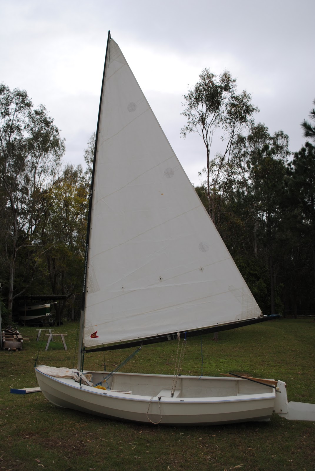
Phoenix III showing-off her sprit rig and flying jib
Despite the simplicity and effectiveness of this rig, I receive a large number of enquiries about the details of setting and reefing, and it appears to me that many people are unsure of how to benefit from its virtues. This is a real pity, because the sprit rig can set a very large sail area from a very short mast, and is a rig which is ideally suited to small boat cruising. In addition, if set properly, it is a good sail for windward work.

Phoenix III tacking away from a Pooduck Skiff in a battle to get up-wind
For me, one of the great joys associated with small craft is experimentation with rig variations, and learning how to make rigs which use an absolute minimum of store-bought fittings. There are plenty of old books about traditional seamanship around, and time spent learning is a good investment.

Below is an except from Phil Bolger's book, 100 Small Boat Rigs (Copyright 1984 International Marine Publishing ISBN 0-87742-182-X)


Back to the 17th century. What I've said about spritsails in Rig 23 ap­plies. By adding a jib to the basic boomless spritsail, some extra area is added in an efficient form, without any multiplication or lengthening of the few short spars. The jib is a good airfoil in its own right, and the draft off it improves the drive of the mainsail. The position of the jib is perfect for a leading-edge device. The spritsail is prone to twist on ac­count of the difficulty of keeping the peak up tight. But the jib compen­sates for the twist to some extent. Taking the jib off doesn't affect the balance of the rig as much as might be thought. If it's sheeted correctly, 10 or 12 degrees out from the centerline, the pull of the sheet tends to swing the bow into the wind. The forward position of the sail has a sur­prisingly small tendency to knock her bow off the wind. By the same token, if you want to make a boat weathercock downwind, as in a broken-down powerboat that won't steer if she gets broadside to the wind, a loose-footed staysail is not the best sail to make her do it.

This is one of the few sloop rigs that can be weatherly without backstays or standing rigging of any sort. The spritsail's mast is so short that it can be built very stiff without its weight overpowering the boat. With the sloop rig the mast is stepped farther aft than in a cat, so the weight of a heavy mast does still less harm.

Moreover, the head of a spritsail is in tension, even when it isn't set up as hard as it should be, and that holds the masthead. The peak halyard of a gaff sail has the same effect, but it's not as powerful because there's less trouble keeping a gaff sail properly peaked: the angle of the halyard to the top of the taller mast of the gaff sail works at a better mechanical advantage. The halyard is also slipping on a sheave, with the vector of its force dividing the angle of the standing part and the fall, while the throat of a spritsail can be lashed, or even shackled, solidly in place.


Of course any cantilevered mast has some give. A big boat with this rig would need something by way of a backstay to get the most drive out of the close-hauled jib. In the 15-footer cartooned, with a 13 1/2-foot mast and sprit, and a jib of 18 square feet, the backstay isn't crucial. The rig is auxiliary to the oars, and since it is a spritsail, the spars can not only be stowed in the boat, but stowed out to the sides to be out of the way of the oarsmen. This is the most powerful and weatherly rig that can meet that specification. The fact that it's a cheap rig, easily built, strong and reliable, easy to maintain, and readily repaired with makeshift material, is an incidental bonus.


For those of you who would like to learn more about the rigging and versatility of a spritsail, there are three exceptionally good illustrated articles available in back issues of Woodenboat Magazine  #89 and #165.  The magazines are available as instant digital downloads for only a few dollars each, and I recommend them to you. Here are links to both issues: -


Sunday, December 22, 2013

Phoenix III in Woodenboat Magazine

In late September this year, I was approached by Woodenboat Publications to see whether I would be prepared to write a "How to Build" article about Phoenix III. I was delighted to be given the opportunity, but the catch was that the manuscript, photos, and drawings had to be submitted in two weeks.


Dan Taylor's home-built Phoenix III sailing in the Pacific North-West USA
(photo courtesy Dan Taylor and Nik Warden)
The writing didn't worry me too much, as I had plenty of material on hand. My major concern was that the plans for Phoenix III represented my very first attempt at using CAD as my drawing medium, and I had to teach myself as I went along. The program used was AutoSketch (from AutoDESK - the makers of AutoCAD) which is a very simple 2D product I use to this very day. Rather than relying on a sophisticated computer program to automatically produce drawings from 3D modelling, I determine the shape of my designs using a variety of methods - from carving a half-model to 3D modelling in DELFTship Professional. Once I have a three-dimensional shape which satisfies me, regardless of the method used, I take dimensions and draw the final CAD plans one line at a time in exactly the same way as I would on a drawing-board - it is just that I use a mouse instead of a pencil, and a screen instead of paper.

The original half-model which provided the starting point for the design


Drawing the lines of Phoenix III a long time ago.
I was not satisfied with the presentation of my early CAD drawings and had for a long time intended to re-draft the Phoenix III plans - not to alter the shape of the boat - just to make the plans more professional. The opportunity provided by the editors of Woodenboat left me little choice, as they wanted a complete set of building plans to accompany the three-part article, and I needed to consolidate the drawings from the previous 30-sheet (A3-sized) presentation to a smaller number of sheets, but making sure that the text and dimensions on the A1-sized sheets would be readable when reduced to the size of a magazine page.

The redrafting process took me about nine or ten days of intense effort, with most days starting early in the morning and running through until about 11pm. After that, I wrote and/or re-edited 16,500 words of text in four days!

One of the new plan sheets
In the same manner as previously, I offer plans in either metric or imperial editions, and they are available in an A3 comb-bound format or as A1 rolled sheets at a substantially higher price due to the printing and postal costs. In both instances, the plans are identical except for the scale of the drawings, with the A3 edition being the standard. As soon as I have a new website published, I will also be offering pdf download editions.

The first part of the three-part article is now on the market in Woodenboat number 236  . You will be able to build the boat directly from the magazine if you wish - all you need to do is to purchase Woodenboat issues number 236, 237, and 238. Certain items will be missing, such as full-sized patterns for side deck hanging knees, boom jaws and oarlock blocks, but the information required to determine their shape is provided. However, the editors (and I) recommend the purchase of a full set of plans if you are serious about building.

Here is a link to a low-resolution video clip of Phoenix III sailing in light conditions, viewed from outside the hull. Despite the low image quality, the clip is worth viewing in order to see how the easily-driven, lean hull slices through the water. Video courtesy of Rick Sutton and Paul Hernes


Thursday, October 3, 2013

Scram Pram - Video Copyright Issues

Some of you may have had difficulty viewing the video I posted on youtube regarding the Scram Pram test sail. Mostly, it seems to effect mobile 'phone reception, but I have made an edited version with the music and music credits (which I printed in full) removed. I hope it works.

Here is the edited VIDEO with just the sailing sounds, complete with the wind distortion, from the camera.

Wednesday, October 2, 2013

Scram Pram Sailing Test Video

Well, it has been a long time since I last posted, but many things have been going on and so I've had to do some "load-shedding" for a while. In the meantime, things haven't been standing still, and among other changes, I now have a new building shed which is 12 metres (40ft) by 9 metres (30ft) under roof,and 12m (40ft) by 6 metres (20ft) enclosed. The shed is insulated against our fierce summer heat and is built to withstand cyclonic winds. In addition to normal (for Australia) 240 volt single-phase AC power, I've got 415 volt three-phase AC hooked up to a couple of outlets. I just need some money now so I can purchase a big 3-phase compressor!!

Shed nearing completion - three big 3 metre Rolla Doors for flow-through ventilation (and drive-through with my truck and trailers), a couple of big windows, and three big spinning roof ventilators. I'm in Heaven!

Being beaten-up by a jealous local thug, while at the same time being protected by my vicious Toy Poodle called Brandy


Both of us very tired, but also very happy!
Since the photos were taken I've moved in a lot of gear, and most importantly, built a 12m x 600mm workbench down one entire side. I've laser-leveled it, and run a 4" dust extraction pipe underneath the length of the bench, with multiple blast-gate equipped inlets spaced regularly.

In February and April I posted some information about a Jim Michalak-designed Scram Pram which I had been working on for a customer/friend, Greg Flemming.  You can see them HERE and HERE

Anyway, my part of the job was finished quite a long while back, and the boat, Nellie, has been in my care waiting for Greg to complete a move and then pick her up for internal finishing and painting. A couple of weeks ago some wooden boat friends were camping out at a local lake, and it was too good an opportunity to miss, so with Greg's permission - encouragement, in fact - I took Nellie for some test sailing.

She performed very well indeed with her Jim Michalak homemade sail, and during the filming we had no water-ballast in the tanks. In the shots from outside, I was sailing the boat by myself, but in the shots taken from aboard you can see that I allowed some local pirates on-board. I did subsequently fill all of the ballast tanks, and she continued to sail superbly. It was nice to be out of the sun and spray, and I can assure you that the boat ventilated effectively from the sail down-draft.

Have a look at the VIDEO and see what you think.


Sunday, June 9, 2013

A Simple Sailing Canoe

Like most of us I have collected a vast number of plans over the years, almost as though having the plans or offsets gives one the possibility of building the boat if required, and that having that possibility is almost as good as having the actual boat.

In 1980 I was reading, among other books, L. Francis Herreshoff's "The Compleat Cruiser" and John Leather's nice little book "Sail and Oar". In "The Compleat Cruiser" is a print of the lines of Francis Herreshoff's interpretation of what he called, a "Rob Roy" double-paddle canoe. What she is, is a half-decked kayak which is wider and shorter than a conventional kayak, and with greater freeboard than normal. She is what Phil Bolger called, "...a canoe-like boat...". Her dimensions were 14' LOA x 26" beam and with a draft of 5-1/4". I found her lines to be absolutely captivating then, and still do today. I hope that one day I may be able to work out how to draw something as beautiful....


John Leather's book re-ignited my interest in sailing canoes at about the same time, and I dreamed of having a sailing canoe with lines similar to the Herreshoff boat.

In mid 1987 (I think) I can remember the excitement I felt when I discovered the existence of Iain Oughtred's plans for the sailing canoe, MacGregor in a copy of Woodenboat Magazine (or the store catalogue). She is a 31"-wide glued-lapstrake sailing canoe which can be built with a length of either 13' 7", 15' 8", or 17'3". I believe that in subsequent editions of the plans, Iain Oughtred only recommends up to 15' 8" LOA. Other options included open or half-decked configurations, and a choice of a cat-rig or a cat-ketch rig. I immediately ordered a set of plans, and finally started building 1991.


At the time of building I was living a hectic life, trying to balance full-time work as an Air Traffic Controller with the responsibilities of helping to bring up our three small sons. This did not leave much time for experimentation with the finished boat, and over the years she received only intermittent use, although she did prove to be a capable sea-boat under paddle-power, having once carried me on a 41 kilometre saltwater journey in 25 knots of wind.

I never did have the proper sail(s) made, but rigged her with the sail off a Bolger Nymph which I had built at an earlier time.

My Bolger Nymph a long time ago

The Nymph sail was of a suitable area, and I set it as a boomed lateen, and that configuration has worked very well on the canoe.

Recent photo of my MacGregor on Atkinson's Lagoon. The rig should be hoisted higher on the mast

Steering is carried out using foot-pedals attached to lines which run to the rudder yoke,  to which I also have a "push-pull" tiller attached.

A few weeks ago, my son, David, and I went for a sail on nearby Lake Wivenhoe. Dave was sailing his much modified Janette which he built for himself at age 14,  (you can read about the boat here http://rosslillistonewoodenboat.blogspot.com.au/2013/03/whimbrel-developments.html ) and I was sailing the  MacGregor. Unfortunately the wind was almost non-existent, but towards the end of the day we got enough to allow Dave to re-familiarise himself with the sailing canoe. Here are a few pictures: -


Although the water was glassy, you can still see that the boat is making some progress due to good technique and careful  sail-setting.

Despite being cooked in our Australian sun, Dave looks content!
The leeboard is ballasted with enough lead to give it neutral buoyancy, and  is held by a strong lanyard above the handle. There is a leeboard guard attached to the hull planking so that the sideways pressure from the sail pushes the board hard against the guard, which is parallel to the centreline of the boat. The leeboard is asymmetrical in section, with a flat outer face and a cambered inner face, which helps it develop lift to windward. When tacking, the leeboard is lifted, turned around so the cambered face will still face inwards, and dropped on the other side. 

A good shot of the boat's trim under sail.

It is important to get crew weight to windward - even in light conditions .

Being able to use the paddle under the sail is a great advantage.

Here is a video shot by Paul Hernes when he and I were at a Wooden Boat Association meet on Lake Wivenhoe. I was sailing the canoe, and Paul was filming from his Phoenix III. When you hear him making a comment about fences, he was pointing out that we were approaching the shore, where there was an old fence from an abandoned cattle property poking up through the water! In the video you can see how fast the little boat is - despite the wind noise in the camera mike, the wind was very light at the time.

http://www.youtube.com/watch?v=eK-4NZrvcZ4

A sailing canoe is such an easy thing to build, store, and transport that I encourage everybody to have a go. You will learn a lot about sailing in a short time, and the costs are minimal.

Saturday, April 13, 2013

Scram Pram Progress

I have previously written about a Scram Pram which I am finishing off for a customer from Sydney. Scram Pram is a design from the board of Jim Michalak, and makes use of the so-called, "Birdwatcher" form of cabin. You can read some of what I have written previously in the post which you can find by clicking this link:-  http://rosslillistonewoodenboat.blogspot.com.au/2012/10/potpurrri.html


The Scram Pram which I am working on was started and taken to about two thirds completion by a builder in Sydney, but work commitments and lack of time prevented him from finishing the job. He asked me whether I would be prepared to finish off the boat, and I told him I would be very glad to do that as it would give me an opportunity to gain experience with the "Birdwatcher"-style of hull.

The boat is now nearing structural completion, and we hope that she will be in the water in a week or two. Internal painting will still need to be completed but we will have a good opportunity to test the boat on the local dam. Below are some photos which may be of interest.


Windows installed, but without bedding compound at this stage.

Windows installed, but without bedding compound at this stage.  The large decks forward and aft, are fitted to the hull using silicon-bronze screws, and set in bedding compound. This allows them to be removed periodically for internal inspection and maintenance. 

The large side windows are simply screwed to the internal faces of the hull-sides, with the screws passing through timber battens so as to cover the unsightly bedding compound, and to spread the point loads so as to help prevent cracking of the Perspex.

This is a view of the leeboard on the starboard side of the boat, looking aft. You can see the 1/2 inch pivot bolt with a very large washer, and at the top the uphaul and downhaul tackle. This is all very simple, although since this photograph was taken I have added a pulley block to the fairlead which you can see on the far right of the photo. This has reduced friction and made the uphaul easier to operate.

 Note the bronze plates which prevent wear on the timber surfaces.
 Note the bronze plates which prevent wear on the timber surfaces.

Scram Pram makes use of water ballast, with three tanks underneath the cabin floor. These are filled and emptied through drains in the bottom of the boat. This photo shows how I modified the brass tube and bung arrangement which was supplied so that the brass tube would not protrude beneath the bottom of the boat, and that water would drain right down to the level of the bottom. The brass tube was cut just long enough to fit the entire length of the bung, and holes drilled laterally level with the bottom of the boat. The block of timber I made to support the tube has been thoroughly sealed with many coats of epoxy, both inside and out.

Here are the same components, but with the bung fitted.

In this view you can see the wooden block, the brass tube, and the bung all fitted permanently to the inside-bottom of the boat. The photograph has been taken looking downwards through a screw-in hatch which is set into the cabin floor. In use, it is an easy matter to launch the boat, reach in through the hatches, and open the bung. When the tank has filled, just replace the bung and screw in the hatch. Emptying is carried out in the reverse manner once the boat has been hauled out onto a trailer.
This is the mast partner which is bolted and glued to the forward bulkhead slightly to port of the centre line. The plan called for either steel or aluminium alloy for the closure plate, but specified half inch thickness. I have taken the liberty of using 8mm aluminium alloy, and set-up the closure plate as a pivoting gate. Time will tell whether this will be strong enough, and also whether it should simply be a plate with two holes and held on by butterfly nuts.

The owner of this boat asked me to modify the design of the rudder so that it did not protrude below the depth of the skeg. In order to do this I designed a shallow rudder with roughly the same area as that shown on the design, but I then added substantial endplates. Testing will prove whether this is adequate.

The rudder is very robust, and the endplate is glued on with epoxy and is supported by a substantial epoxy fillet reinforced by 450GSM woven glass. This should be strong enough to act as a step to assist people re-entering from the water.

I also shaped the upper edge of the rudder so that a foot can be placed on it without sliding off. The combination of the endplate, top of the rudder, and the outboard motor well should make for a serviceable ladder.

This shows the tiller position looking aft towards the rear bulkhead.


Here you can see the leather chaffing guard sewn around the mast where it enters the partner.

This is leathering on the yard at the point where the halyard is attached. The lump in the middle is the leather sewn around a commercial fairlead.

Here you can see leather glued to the started side of the boom, which in this view is upside down. The downhaul is attached through the black cleat and pulls downwards when the boat is rigged.

This is a pulley block with beckett attached to a pad eye which has been very securely screwed to the masthead. The mast is square sectioned and solid Hoop Pine.
Once the boat has been launched and initial test sailing has been conducted, I will publish another post.

Water Rat in 4mm Plywood - Sailing Version?

Water Rat is a 3 foot wide plywood kayak which can be built with a length of either 9' or 10'10". This boat has an unusual, but attractive shape, and has proved to be quite popular. She was initially drawn by my friend Doug Laver back in the days when we were working at my workshop in Brisbane, and we had started experimenting with Gregg Carlson's Hull Designer program.The plans that Doug and I used originally were very difficult to interpret when it came to the shape of the developed panel sections, and I subsequently redrew them in a CAD program, incorporating a few variations and conventional dimensioning. You can read about the boat in a previous post here:-    http://rosslillistonewoodenboat.blogspot.com.au/2011/11/water-rat-developments.html

Doug's original Water Rat with my son, Steven, showing off the boat's stability. Steve was about 12 then, and I haven't seen this activity performed by an adult - but for a canoe she is a very stable boat.


Ross Trinder, from Toowoomba in Queensland, Australia, has built a number of boats recently including a Green Island 15, one of my First Mates, and a Water Rat. My good friend Al Burke also built a Water Rat, but used 4mm plywood instead of the 6mm plywood specified. Al applied some strategic stiffening materials and as you can see in the comments, his boat weighed in at 17 kg.

Ross Trinder is now building a second Water Rat, and this time he also is using 4 mm ply. Another variation on the theme being experimented with by Geoff Leedham in his boatbuilding program at a school in Alice Springs, Outback Australia, is to use 4 mm plywood for the entire boat with the exception of the bottom panel, which is made from 6 mm plywood.

This boat is a very simple project which involves very little time and very little money. However, it represents a great way to gain experience in the use of  epoxy and plywood, and the resulting boat is great fun to use, is very stable, and is surprisingly seaworthy in protected waters.

Ross Trinder has asked me whether it would be practical to fit Water Rat with a sailing rig. Given that she is 3 feet wide and carries her breadth out into the bow and the stern, I think that she would be able to carry sail reasonably well, and the only real challenge is to decide how best to give her some lateral plane. My first reaction is to make use of the leeboard, but I'm beginning to think that an off centre dagger board would suit the boat very well. I will be doing some preliminary drawings shortly, and will post them here.

In the meantime, here are some photographs of the early stages of construction of Ross Trinder's 4 mm Water Rat. You can also see Al Burke's finished 4 mm version via the link at the end of the first paragraph.

In this photograph the panels and bulkheads have been cut out accurately, have had holes drilled along the edges of the panels, and the boat assembled using plastic cable ties. After having ensured that there is no twist in the boat, Ross has placed a series of short tabs of thickened epoxy between the cable ties in the forward and middle sections of the boat.

Here you can see how the "tack-welds"of thickened epoxy remain clear of the cable ties, and are very small in cross-section. After the epoxy has cured, the cable ties will be removed and a larger fillets of thickened epoxy will be applied in a continuous run over the top of the "tack-welds" and have glass tapes laid over them while still wet.

Note how the bow and stern transoms, and the bulkheads, have centrelines marked. These are lined up with the centreline on the bottom panel, and as long as there is no twist allowed, the boat must come out the correct shape - even though there is no strong-back or mold.

Here you can get a good idea of the shape of the boat, and as long as the panels are cut out accurately, the shape of the boat is smooth and fair. This particular boat goes together very easily, and it may be possible to get away with as few as half of the cable ties you see in the photo.


Thursday, March 28, 2013

Voice recognition software

I am writing this short post in order to test the voice recognition software embedded in Windows 7. It is my hope that I can write posts more frequently in this way and also answer my backlog of emails.

My primary work is boatbuilding and design and I am finding it difficult to keep up with the administrative work which articles, emails, and the blog entail.

At the moment I am teaching the software how to recognise my Australian accent, and it seems to be having great difficulty!

There will soon be posts about a Water Rat being built from 4 mm plywood which is coming along very nicely indeed, and I will be posting some photographs of the Scram Pram which is almost completed. The windows are in and we hope to have the boat in the water within a few weeks for trials.

The voice recognition software seems to be working, but please be tolerant of my mistakes!

Ross Trinder's beautifully built 4mm Water Rat


Scram Pram with her windows dry-fitted, and the decks screwed down on bedding compound

Now, doing all of that with voice-recognition software was VERY time consuming, but stand-by for an improved service!

Thursday, March 7, 2013

Whimbrel Developments

My plans for Whimbrel have been sitting 90% finished for a long time. The drawings which have been finished are nicely detailed, and I really like the boat. But for some reason the final step of completing the plans for publication has been very difficult to complete.

Outboard Profile of Whimbrel, showing her with the original balance lug rig and free-standing mast. Note how the heel of the mast has to swing down and up through the foredack. This arrangement is catered for by the installation of a slot-type box - similar to a centreboard case, but upside-down.
Whimbrel was designed with a balance lug mainsail, and to capitalise on some of the advantages of this rig (no headsails, no sail-track or lacing, self-vanging boom, simple and effective reefing) the design was drawn with free-standing masts. An important component of the rig was to be a main-mast set in a tabernacle, so as to allow quick and easy rigging and un-rigging for trailer transport, and for reducing windage when on a mooring in bad weather. You can see the lowered mast position in dotted lines on the drawing above.

Tabernacles can be bulky affairs, and I dislike having a tabernacle which extends a long way above the deck line. However, a free-standing mast benefits from substantial "bury" of the mast within an arrangement of mast step and mast partners, or, as in this case, within a tabernacle. My approach was to have the base of the mast swing up and down through a slot in the foredeck, with sides to the box which extend all the way to the level of the mast step. That way, water can drain down the mast, or come on deck as spray, and it simply runs down to the bottom on the mast case and is then drained over the sides through scuppers - making the mast case self-draining.

The design of the slot and case was fairly straight forward, and I was very pleased with how the structural members support each other and go together in a logical fashion. The trouble is that although the mast case (i.e. a structure similar to an upside-down centreboard case) is simple to construct, it was and is very difficult for me to explain on paper. The drawings of all the components are complete in a 2D form, but I do not have the skills to operate the 3D CAD program I have on hand (TurboCAD 17). I do all of my CAD work in an AutoCAD 2D program (AutoSketch 9).

Several times I've tried to do a simple diagram as an "exploded" isometric drawing, but nothing satisfying has eventuated. I thought that the simplest thing would be to build a prototype, and photograph the case construction in detail, as I was/am sure that as soon as people see it, they will appreciate the simplicity and structural elegance.

In the meantime, one of my sons has been experimenting with a tiny jib (set flying) on a small clinker/lapstrake dinghy he built years ago. The small jib has boosted the windward performance of the boat enormously, even though the sail area of the jib is only 11sq. ft (from memory). This boat sailed quite badly with the free-standing rig as originally built, using a carbon windsurfer mast. The mast was just too soft, even with the addition of substantial alloy sleeve at the lower end.


Here you can see Dave's boat sailing with the original free-standing mast. She had initially sailed with the sail made according to the sail-plan on the plans, but that sail had been awful. Perhaps it would have been ok on a stiffer mast instead of the windsurfer stick. We then changed to an old Laser sail as shown in the pictures, but the mast was still far too soft, and the boat was a very poor performer to windward.

I've told this story before on the blog, but I suggested to Dave that we put some stays on the rig, with the point of attachment (hounds) being just a fraction over halfway up from the deck to the masthead. He was reluctant, but I eventually convinced him to give it a go and we made up a forestay and two shrouds using Dyneema/Spectra. This also allowed us to set an old jib, as a "flying jib" i.e. a jib with is not attached to the forestay with hanks.


The performance of the boat was dramatically transformed for the better, and the boat is giving great service.

My point in re-telling parts of the rig story is to illustrate that sometimes a very modest increase in complication can result in huge gains in performance. Now, back to Whimbrel....

The revelations about performance brought about by the addition of the jib to Dave's boat got me thinking a little outside the box I normally occupy. I tend to be a bit obsessive when it come to rig simplicity, because I hate clutter in a boat when rigging and un-rigging at the boat ramp. Our experiments with the dinghy rig above have brought me to the point where I'm considering some different rigging arrangements for Whimbrel, and the design evolution continues - perhaps it was fortunate that I hung off from completing the original drawings.


In the above drawing you can see the proposed new rig for Whimbrel. The hull is unchanged, as is the mizzen, but the main part of the rig is now a lightly stayed, gaff-headed mainsail with a staysail set on the forestay. The staysail can either be hanked onto the forestay, or could be permanently attached to the forestay with a simple roller-furling tackle set at the tack.

Because the mainmast is now supported by stays in the form of a forestay and two shrouds, the mast no longer requires the support of a tabernacle which runs deeply into the hull. In this case the tabernacle is short and extends only to the level of the deck, and the foredeck is no longer cut up by a mast case and slot. So the mast is significantly shorter at the foot, and the diameter of the mast is reduced from 92mm (3-5/8") to 65mm (2-9/16").

Whimbrel set up for the night with a boom tent rigged and the mizzen sheeted flat to hold he head -to-wind.  I can't see the anchor rode - it must be some of that invisible rope I sometimes use!


I'm continuing to consider some options for the cockpit, and will up-date soon.