
Sunday, April 5, 2015
Several Videos added to bottom of Website Footer
I've added several videos to the bottom of the listing on the video page of my website - see video link on the footer of the home page.
Saturday, April 4, 2015
Image Galleries on Website
After a lot of time spent learning about the intricacies of the dashboard on the new website, I have now been able to expand the list of picture galleries, and I have some images on every gallery.
This is very time consuming due to my ignorance when it come to working with Wordpress, but I have made significant learning progress over the last couple of days, and the site content will continue to grow.
The next thing I'll be doing is getting captions onto the gallery images, but it will be a gradual process over a week or so. Also coming in the near future will be extra pages in the 'Designs' section.
Thursday, April 2, 2015
Micro Repair
Phil Bolger's Micro design is a favourite of mine, and of many other people around the world.
To the uninitiated, the boat looks somewhat like , well..., a box. The hull cross-section is, in fact, perfectly rectangular - something which leads many observers to underate the design and write it off as a crude and simple piece of work.
Well, Micro is a very simple boat to build, but only a genius - someone like Phil Bolger or Naval Architect C. Raymond Hunt - could design such a hull and make it work well (Phil Bolger was heavily influenced by C. Raymond Hunt, among others). It takes understanding to get the best from Micro and her free-standing cat-yawl rig, but if treated properly, she is an exceptionally good performer, while at the same time being cheap and quick to build, self-righting and self-bailing, roomy, and comfortable - all in a 15-1/2' x 6' x 18" package.
I'm not going to go into detail about the design aspects of the boat, but I will say that on one occasion I sailed her against a well-handled Navigator and an equally well-handled Penobscott 14, and even though I had two passengers, we beat both boats to windward, and pointed just as well. Now, the conditions were ideal for Micro, in that we were on a lake with about 10 knots of breeze and almost flat water, but her performance was superb, surprising me as much as anybody. It might have been different in a steep chop....
This particular Micro has been back to my various workshops on a number of occasions in order to have cockpit modifications made, and to have repairs carried out. Most recently, she came back to me after having been in collision (head-on) with a concrete floating walkway/wharf beside a boat ramp.
The damage was fairly localised around the bow transom and forward topsides, but Micro has a wonderful self-draining well, right between the bow transom and the forward bulkhead of the cabin, with a strong set of floorboards filling the space between the bow and the cabin bulkhead. The floorboards are at approximately the level of the painted boot-top (i.e. the division between the green and cream just above the waterline in the photo below).
When Cricket hit the concrete walkway, the point of impact was head-on, almost exactly at the level of the floorboards. This not only damaged the bow transom, but also forced the floorboard panel back through the forward cabin bulkhead with great force. Micro is not a particularly light boat, carrying 195kg/412lbs of cast lead in her keel, weighing-in at around 500kg/1/2 a ton - so the damage was substantial.
Micro has a primary structure made from 6mm/1/4" marine plywood for the most part, with a substantial amount of 3/4" framing timber throughout in various widths. The boat relies on her large volume and surface area for her structural strength, and is well designed from an engineering perspective. However, like many aircraft, she is structurally strong, but vulnerable to point impacts.
The point of this post is to let people know that with careful planning and execution, a wood/epoxy boat can almost always be repaired to as good a standard (or better) as when she was built. Do not skimp on the process and avoid any temptation to "plaster over the cracks" so to speak - attention to structural detail is essential.
I may write more about the repair process use on this boat in a later post (no promises), but here are a couple of photos of the structurally complete repair, with only a few remaining paint details to be finished.


The repair process involved a lot of debris removal, fabrication of simple jigs to regain the correct hull shape, re-lamination of damaged plywood sheeting, plenty of epoxy, epoxy fillets, and glass fabric reinforcements - but the boat is alive and well!
The moral of the story is to build your boat properly in the first place, and repair her with care if the need arises. Have an open mind and be prepared to be inovative and to improvise. There is no reason why a home-built plywood boat should not last several lifetimes, even if damaged along the way. In fact, if you are not under too much time pressure, the process can be both challenging and rewarding.
To the uninitiated, the boat looks somewhat like , well..., a box. The hull cross-section is, in fact, perfectly rectangular - something which leads many observers to underate the design and write it off as a crude and simple piece of work.
Well, Micro is a very simple boat to build, but only a genius - someone like Phil Bolger or Naval Architect C. Raymond Hunt - could design such a hull and make it work well (Phil Bolger was heavily influenced by C. Raymond Hunt, among others). It takes understanding to get the best from Micro and her free-standing cat-yawl rig, but if treated properly, she is an exceptionally good performer, while at the same time being cheap and quick to build, self-righting and self-bailing, roomy, and comfortable - all in a 15-1/2' x 6' x 18" package.
 |
| Cricket - a Micro which I built back in late 2001/early 2002. |
 |
| In this photo you can see some of Micro's unusual features - flat bottom, extreme rocker, and rectangular sections. Very few people could design such a boat and make her a success. Very few people understand why the hull and rig work so well. |
This particular Micro has been back to my various workshops on a number of occasions in order to have cockpit modifications made, and to have repairs carried out. Most recently, she came back to me after having been in collision (head-on) with a concrete floating walkway/wharf beside a boat ramp.
The damage was fairly localised around the bow transom and forward topsides, but Micro has a wonderful self-draining well, right between the bow transom and the forward bulkhead of the cabin, with a strong set of floorboards filling the space between the bow and the cabin bulkhead. The floorboards are at approximately the level of the painted boot-top (i.e. the division between the green and cream just above the waterline in the photo below).
 |
| My youngest boy, Steven, standing in the forward well back in 2002. He is standing on the forward well floorboards. |
.jpg) |
| Winch post pad covers most of the external damage. The paint is the original Hempel Polybest two-pack polyurethane which I applied in 2002! Notice how the plywood of the topside panels has de-laminated and split away from the bow transom framing. The damage is much worse than it appears. |
.jpg) |
| Photograph of the inside of the forward well, looking towards the bow transom. The two large holes in the transom are the steps of the boarding ladder! (there is a hydrodynamic reason for the transom at the bow, but that is another story). You can see how the bow transom has been driven backwards through the topside panels, and that the framing has suffered serious structural trauma. In addition the planking-to bow transom epoxy fillets have been more or less destroyed. |
.jpg) |
| Looking aft at part of the damage inflicted to the forward cabin bulkhead by the floorboard assembly. The boxed opening at the far left of the photo is the cabin ventilation opening - lets air through but keeps water out... |
 |
| External damage to the starboard side of the bulkhead after initial paint removal... |
 |
| ......and the same on the port side. Doesn't look too bad, but represents serious structural damage on close inspection from inside and out. |
Micro has a primary structure made from 6mm/1/4" marine plywood for the most part, with a substantial amount of 3/4" framing timber throughout in various widths. The boat relies on her large volume and surface area for her structural strength, and is well designed from an engineering perspective. However, like many aircraft, she is structurally strong, but vulnerable to point impacts.
 |
| Bulkhead damage |
 |
| Damage to the bow |
 |
| Damage to the bow. |
I may write more about the repair process use on this boat in a later post (no promises), but here are a couple of photos of the structurally complete repair, with only a few remaining paint details to be finished.
 |
| Just some painting to be done over the white two-pack epoxy primer/undercoat visible at the forward end of the keel, and some black boot-topping to be painted as well. |
The moral of the story is to build your boat properly in the first place, and repair her with care if the need arises. Have an open mind and be prepared to be inovative and to improvise. There is no reason why a home-built plywood boat should not last several lifetimes, even if damaged along the way. In fact, if you are not under too much time pressure, the process can be both challenging and rewarding.
Wednesday, April 1, 2015
Website and Blog - Making Progress Slowly but with Determination!
Those of you who have been patient enough to be checking back to see how progress is going on the new website and the blog deserve an explanation about what is happening.
Due to an excess of work and looming deadlines, I've been caught between devoting time to the workshop and to development of the new website and the blog. Jobs in the workshop are well in hand (and must take priority), but by September my contracted work will be complete, and I'll then be turning my attention to fun jobs in the workshop, and lots more writing and design work. With good luck and sensible management, this should result in lots more articles and the publication of a stack of designs I have sitting in the wings waiting for finishing touches. Yes, I know you may have heard me say such things before, but I really am ploughing through the work at the moment, and I have for many months now had a moratorium on taking on any new building/repair work.
Tomorrow I'll post some photos of recent work, and a list of current jobs. One particularly interesting project is the building of a sixteen-sided mast for a large sailing dinghy. This mast is unusual in that it is not only hollow, but the wall thickness tapers as the mast tapers, so the wall-thickness as a percentage of mast diameter remains constant. Another interesting feature of this mast is that it incorporates an 'in-mast' hinge - sort of like a tabernacle without a tabernacle (see Woodenboat Magazine #237 for the idea)
The sixteen-sided method is probably too labour-intensive to be practical without a production set-up, but the experiment has provided me with valuable insights, and has been R&D time well spent. Maybe eight-sided next time? The method does have advantages over the Bird's Mouth method, mainly in providing the ability to taper wall thickness as well as diameter - all in a home workshop.
I'm just beginning to come to grips with some of the complexities of the website program and associated plug-ins, so there will be gradual (but accelerating) addition of content and pages. Further down the track will come video tutorials on some interesting stuff.
Facebook and Twitter have me somewhat stumped at the moment, but that will improve with time - especially after workshop commitments are complete.
Due to an excess of work and looming deadlines, I've been caught between devoting time to the workshop and to development of the new website and the blog. Jobs in the workshop are well in hand (and must take priority), but by September my contracted work will be complete, and I'll then be turning my attention to fun jobs in the workshop, and lots more writing and design work. With good luck and sensible management, this should result in lots more articles and the publication of a stack of designs I have sitting in the wings waiting for finishing touches. Yes, I know you may have heard me say such things before, but I really am ploughing through the work at the moment, and I have for many months now had a moratorium on taking on any new building/repair work.
Tomorrow I'll post some photos of recent work, and a list of current jobs. One particularly interesting project is the building of a sixteen-sided mast for a large sailing dinghy. This mast is unusual in that it is not only hollow, but the wall thickness tapers as the mast tapers, so the wall-thickness as a percentage of mast diameter remains constant. Another interesting feature of this mast is that it incorporates an 'in-mast' hinge - sort of like a tabernacle without a tabernacle (see Woodenboat Magazine #237 for the idea)
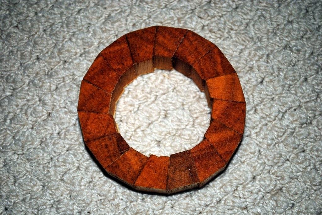 |
| Here is a slice off a test section of my mast construction method. There is a very good reason for the angle being cut into one side of each stave, rather than half the angle being taken of each side as they used to do it in the old days. Maybe I tell you why some day... |
I'm just beginning to come to grips with some of the complexities of the website program and associated plug-ins, so there will be gradual (but accelerating) addition of content and pages. Further down the track will come video tutorials on some interesting stuff.
Facebook and Twitter have me somewhat stumped at the moment, but that will improve with time - especially after workshop commitments are complete.
Saturday, February 7, 2015
New Website - Currently on the steep side of the learning curve
For those of you who may have subscribed to the new website, I have an uncomfortable feeling that you may have been deluged with "New Posts" as I have been progressing with the process of learning the new software characteristics. If so, please accept my sincere apologies.
The good news is that I'm reading and experimenting diligently, and progress is starting to take place. I hope to get the 'Designs' section and the embryo 'Shop' looking more professional in a few days.
Concurrently, I'm working on the construction of a new mast for a customer, and it promises to be a major step forward in 'home-workshop-buildable' masts and other spars, without the need to cut 'Bird's Mouth' profiles. Many people don't understand that very small errors in the setting-up of the saw or router for 'Bird's Mouth' staves can have a huge effect on the diameter of the finished spar. Also, unless you have a very well arranged table-saw or router table, the potential for disaster is substantial...
They say that, '..pride comes before you end up with mud on your face...', but I'm quietly confident that the prototype mast I'm making will be faster, safer, and easier to build, and will have one REALLY substantial advantage over a 'Bird's Mouth' spar in that the wall thickness as a percentage of spar diameter will remain constant over the length of the mast. In the case of a 'Bird's Mouth' mast, the wall thickness (in percentage terms) increases as the mast tapers towards the tip - so much so that many masts become effectively solid towards the tip - not what is wanted at all! We need to keep masts light - especially as we go higher.
More to come when I get through this website business.
I've got a number of boats under construction or repair, but design will dominate before too long.
Monday, February 2, 2015
New baysidewoodenboats.com.au Website (almost) up
For several days now, the skeleton of my new website has been up and running.
This has been a longtime coming, mainly because of my relative ignorance of things to do with computers and IT.
My previous website was brought into existence to give people access to the vast number of construction and rigging photos which I have available, and to save me the costs and, primarily, the time involved in sending repetitive emails to enquirers needing help and illustrations - a picture being worth a thousand words, I'm told...
Because of my general ignorance of matters relating to computers, I decided to use the most simple of programs, even though many people had told me it was out-of-date. That program was Microsoft FrontPage 2003, and it has served my very well indeed. I was able to follow the simple templates, and before long, I had a website which was simple to navigate (lots of basic buttons on the left-hand side of each page) and allowed me to put up many expandable-thumbnail galleries.
Despite my lack of computer knowledge, and scant knowledge of graphic design, the amateurish website has pulled in an average of between 2.7 and 3.4 million hits per annum for many years. That is page hits, by the way, not numbers of visits - but still not bad.
The new website, which is WordPress based, will display better on mobile devices, will support a shopping cart, will interface with social media (another thing I know almost nothing about), and will incorporate this blog and lots of other things - including, hopefully, a forum. That way YOU can be involved.
For those of you who have already subscribed, please be patient. I will be having a meeting with the website developer, (Julie from http://www.360results.com.au/) on Wednesday, February 4, and that is when control of the site will be handed over to me for further action - at the moment I can't respond to subscriptions. Julie has done a great job, but has only had a few bits of content from my old website to use in filling out the page content. Once I have official control, and have learnt how to drive the site, I'll start filling up the pages.
In addition to a lot of videos and new plan information, I will be starting to run an on-line shop which will market fittings, books, boatbuilding supplies such as paint, plywood, fibreglass, fastenings, specialty glues, epoxy, and sails etc., etc., Because of my one-man-band status, the development will take a little time. As for the stock in the store, I will be partnering with a selection of very well-known companies, and the materials on offer with be of very high-quality. For overseas customers in particular, my plan sets will be available as instant PDF downloads in addition to the existing printed sets. Printed sets are nice, but the postage which I pay can be as high as AUD$36 for some of the plans. I don't charge that much, so it has a big impact on the viability of my chosen business.
Finally, I am in the process of up-grading my design software, which until now has been of the most basic type. Disregarding hull modelling, which I do in a combination of 3D modelling programs, carved half-models, and hand-drawn lines, my actual plans drawings are done individual line-by-individual line (i.e. manually) using a basic 2D CAD program - AutoDESK (the AutoCAD people) AutoSKETCH 9. Most of my plans contain between 16 and 32 sheets of A3 paper, plus illustrated instruction booklets of up to 70 pages, so the production of a set of saleable plans represents a HUGE investment of time.
My proposed path into the 21st century with regard to drafting should result in better plans presentation, and with luck, exploded diagrams of sub-assemblies.
So folks, thank-you for your patience and support over the years, and stand-by for a bit more action and communication!
Friday, October 24, 2014
Following up on some comments
In relation to my post, "Lugsail Performance - Better than you may Imagine", Simeon writes: -
Well, I have been very lax both in the writing of posts, and in the answering of comments. I'm sorry for that - it has been a combination of building a house, trying to catch-up of long overdue work (and in the process, putting food on the table), and having more plumbing work done on my heart (currently up to nine stents). Still, it is not an excuse for me being rude and dismissive.
Regarding the method of improving the performance of a lugsail when sailing on the wind, a clue lies in the sheeting arrangement on a Chinese lugsail.
The system I use to improve the performance of a lugsail is a very simple vang which which leads to the head of the yard. This vang system can also be used effectively with all varieties of lugsail (balance, standing, and dipping), the sprit rig, and the gaff-headed rigs of differing styles.
Most people are familiar with boom-vangs, but the vang I'm showing here operates at the top of the sail, and unlike boom-vangs, it is very lightly loaded, requiring only a light line. This is not an idea of mine - vangs like this have been in use so centuries - however, I suspect that my method of rigging and adjustment is novel.

In the above drawing, I've shown a small boat with a balance lugsail set close-hauled. For the sake of clarity, I have omitted the mainsheet from the sketch.
The vang is simply a length of 3mm (1/8") VB-cord made fast to the head of the yard. In the case of a sprit rig the vang attaches to the upper end of the sprit, or to the outer end of the gaff for a gaff-headed rig.
I have drawn the vang in red, and it runs down to a thumb cleat on the weather side of the transom, across to a simple fairlead on the rudder head, and then along the tiller to a small V-Jamb cleat or a little cam cleat located in a convenient position to allow adjustment. There is very little load on the vang, and it is quick and easy to adjust.
The vang is lead to the weather side so that the angle it makes up high is not too acute, therefore increasing the mechanical advantage. When tacking there is no handling required, because the vang slips out from under the thumb cleat of its own accord as the sail moves across the boat. After the tack has been completed and the boat has settled on the new course, it is a simple matter for the skipper to reach over and grab the vang as it blows out in a smooth curve from head of the sail down to the rudder, and slip it under the thumb cleat on what has become the new weather side of the transom.
For up-wind sailing, this simple vang allows one to adjust the amount of twist in the sail from boom to yard (or gaff, or sprit), greatly improving performance if the crew knows what they are doing. Some will tell you that you should have twist in a sail to take into account "wind gradient". Well, full-size empirical testing has shown that such a thing may be of value at very low wind speeds, but once the wind speed exceeds 6 knots, you are better off with minimum twist.
Sailing downwind, the very same vang can be used to prevent the yard/sprit/vang from going beyond 90 degrees to the centreline of the hull (70 or 80 degrees is better), therefore avoiding the dreaded "death roll".
I know you've been busy
with First Mate but some of us fans are still waiting for illumination on your
comment from an earlier blog entry:
"In a later post I'll show you how you can improve the windward performance of the lugsail even more, using nothing more than a short length of V.B. cord."
"In a later post I'll show you how you can improve the windward performance of the lugsail even more, using nothing more than a short length of V.B. cord."
Well, I have been very lax both in the writing of posts, and in the answering of comments. I'm sorry for that - it has been a combination of building a house, trying to catch-up of long overdue work (and in the process, putting food on the table), and having more plumbing work done on my heart (currently up to nine stents). Still, it is not an excuse for me being rude and dismissive.
Regarding the method of improving the performance of a lugsail when sailing on the wind, a clue lies in the sheeting arrangement on a Chinese lugsail.
 |
| My old boat, which is still sailing after 45 years, here sporting her Chinese Lugsail back in about 1990 |
The system I use to improve the performance of a lugsail is a very simple vang which which leads to the head of the yard. This vang system can also be used effectively with all varieties of lugsail (balance, standing, and dipping), the sprit rig, and the gaff-headed rigs of differing styles.
Most people are familiar with boom-vangs, but the vang I'm showing here operates at the top of the sail, and unlike boom-vangs, it is very lightly loaded, requiring only a light line. This is not an idea of mine - vangs like this have been in use so centuries - however, I suspect that my method of rigging and adjustment is novel.
The vang is simply a length of 3mm (1/8") VB-cord made fast to the head of the yard. In the case of a sprit rig the vang attaches to the upper end of the sprit, or to the outer end of the gaff for a gaff-headed rig.
I have drawn the vang in red, and it runs down to a thumb cleat on the weather side of the transom, across to a simple fairlead on the rudder head, and then along the tiller to a small V-Jamb cleat or a little cam cleat located in a convenient position to allow adjustment. There is very little load on the vang, and it is quick and easy to adjust.
The vang is lead to the weather side so that the angle it makes up high is not too acute, therefore increasing the mechanical advantage. When tacking there is no handling required, because the vang slips out from under the thumb cleat of its own accord as the sail moves across the boat. After the tack has been completed and the boat has settled on the new course, it is a simple matter for the skipper to reach over and grab the vang as it blows out in a smooth curve from head of the sail down to the rudder, and slip it under the thumb cleat on what has become the new weather side of the transom.
For up-wind sailing, this simple vang allows one to adjust the amount of twist in the sail from boom to yard (or gaff, or sprit), greatly improving performance if the crew knows what they are doing. Some will tell you that you should have twist in a sail to take into account "wind gradient". Well, full-size empirical testing has shown that such a thing may be of value at very low wind speeds, but once the wind speed exceeds 6 knots, you are better off with minimum twist.
Sailing downwind, the very same vang can be used to prevent the yard/sprit/vang from going beyond 90 degrees to the centreline of the hull (70 or 80 degrees is better), therefore avoiding the dreaded "death roll".
.jpg) |
| In this photo of Phoenix III at rest, you can just make out the 1/8"/3mm vang blowing out in the breeze behind the sail. Obviously it has been completely loosened off, but it gives an idea. |
Subscribe to:
Comments (Atom)