Sunday, April 22, 2012

"Fleet" launched

Fleet has had her launching day, and so far the performance report has been very satisfactory. Launching was said to have been as hectic as such occasions usually end up being, and the owner/builder thinks that at least thirty people had a go in the boat.

The engine used was a brand-new-out-of-the-box Suzuki 6hp four-stroke, and it was able to get the boat onto what felt like a plane with three heavy adults aboard. As there was no GPS available, accurate speeds were not recorded. As hoped, the ride was very smooth in a chop and through boat wakes, but there was no opportunity to get out into the ocean waves outside. What I find very satisfying is that the boat trimmed nicely when throttled back somewhat and remained dry throughout the tested speed range.

Tight turns at speed were stable and predictable.

Due to the business of the day, organised photography was not carried out, but here are a few snap shots. We plan to carry out more serious testing with 2.5hp, 4hp, 6hp, 9.8hp and oars.

A good view of the general proportions
Trim at rest with two adult men aboard
Running with the weight of two adults, under the urge of a new (and therefore tight) 6hp four-stroke Suzuki

Saturday, April 21, 2012

More photos of "Fleet", the planing version of "Flint"

The first example of Fleet, the planing hull version of Flint is getting much closer to launch day. In fact she has already been in the water to allow the marking of the waterline in preparation for the painting of the boot top - empirical data gathering!

Painting has gone ahead at a great rate, using the skills of people who normally apply coatings to aeroplanes and helicopters.

First real opportunity to view the hullform in the flesh.

 The hull shape is similar to the designs of the late William H. Hand, said to have been the inventor of the vee-bottomed motorboat. What made the William Hand designs significant was the way they would handle well at lower speeds when throttled back. Weston Farmer said of them, "They were steerable throughout their entire range of speed in following seas. The full planing boat is a dog in this department. Unless they are banging along full bore, you cannot steer them. And full bore in some seaways with this type of boat, demands Polident for the helmsman's teeth and metal brassiers for the ladies." ("From My Old Boat Shop" International Marine 1979.) Now, I think planing hull design has come some way since Weston Farmer formed his opinion, and there are some very fine designs around for full planing hulls, but the fact remains that for moderate planing and semi-planing speeds, a long, narrow Hand-style hull can be superb.

Getting ready for a trip down to the boat ramp for waterline marking. Gunwales are masked, as they will be finished bright using Deks Olje #1
First splash. Chines don't even touch the water when light. I hope that with a single oarsman on the forward thwart, the boat will be reasonably pleasant to row, even though she is a planing hull. Trim will be everything with passengers aboard.
25 litres of water in the aft well to represent the outboard and fuel, plus two people. The fellow on the helmsman's thwart is quite light, but the trim is very close to that predicted on the plans.
After the floatation tests, marks were made to allow masking-off for the boot-top.

Note the chinagraph pencil marks at the base of the stem.
Boot top masked ready for topside painting
Here you can visualise the fine, sharp lines up for'ard - she should give a smooth ride at moderate speed in a chop.
Almost ready for the water - just the oiling of the gunwales and breakwater/coaming to go. Test motor will most likely be a 6HP 4-stroke, but that is to be confirmed.

Thursday, April 19, 2012

Update on Low-powered planing hull "Fleet"

Since my last posting about Fleet, the planing version of my row/sail boat, Flint the owner/builder has been burning the midnight oil to get her finished. Here are a few photos to show progress, with a performance report to come in about three days time. The painting is proceeding rapidly, being done in an aircraft component spray booth!

Hull sanded, chines rounded-over, and 200gsm/6oz glass cloth being draped
Glass/epoxy sheathing. Given the work that was done on the bottom panel (see previous post) the cloth has been doubled in the forward sections of the bottom of the hull.
Glassing completed, and hull surface sanded. 12mm/1/2" gunwales have been added.
Spaced inwales being dry-fitted
The spaced inwales are of quite generous section on this particular boat, as the owner/builder will be using her in surf and unprotected waters on the Australian east coast for serious fishing. There are a number of other ways the topsides could be terminated, including side decks or simple laminated gunwales on the external surface only.
Being moved from the building location to the paint booth. The first opportunity to see her from a distance.
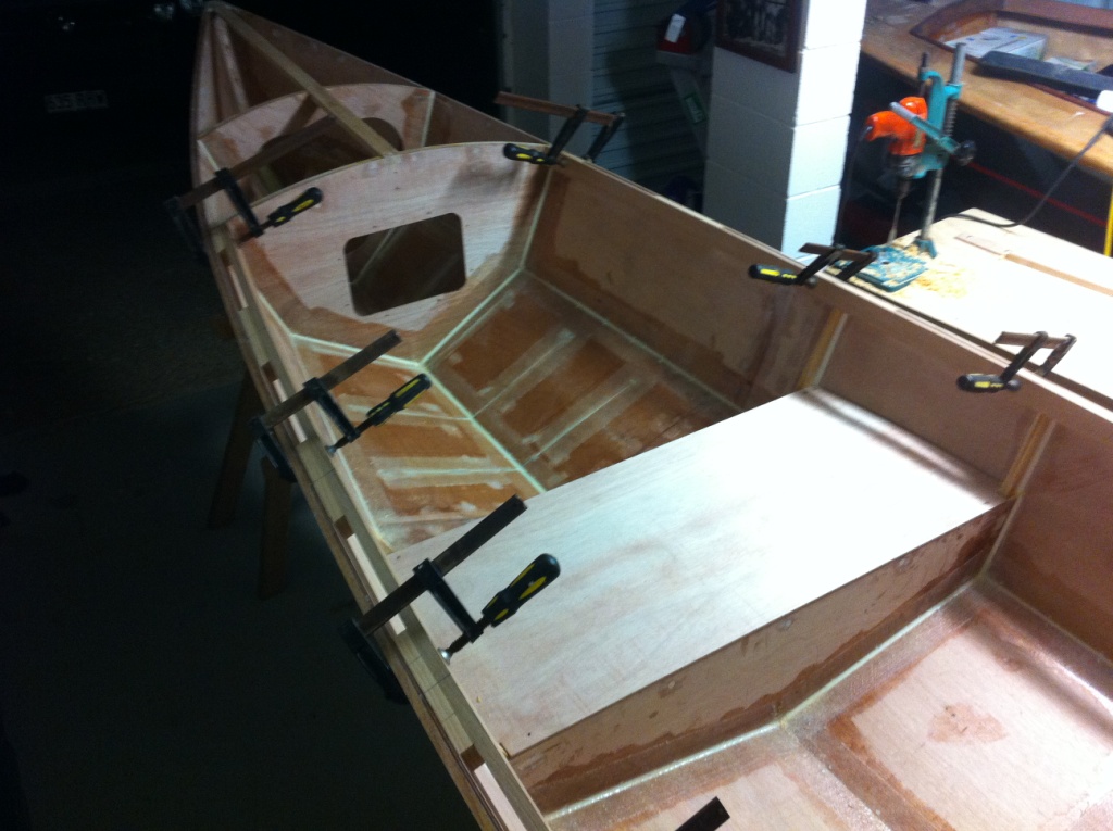
View of the interior showing some of the generous emergency buoyancy compartments. The large rectangular hatchs are non-standard, and are being used by this owner (who is a very experienced oceanic fisherman) for fishing equipment
First view of her profile
Coaming/breakwater and toe-rails added
In the paint shop - will be completed in about another 24 hours.
As I mention previously, I believe that there is a genuine need for small powerboats which have been optimised for operation under the urge of very small outboards. I nervously await the performance report from the first outing, which will be within the next three days. This example with be pushed by a 5hp Mercury, and has been built a little heavier than initially planned due to the rugged duties expected of her. A very light version, built in a manner similar to Flint, should go well with 2-1/2 to 4hp.

Wednesday, April 4, 2012

Low-powered planing hull - lessons learnt

Just before leaving on our recent road trip (4,500km), I wrote a post about a planing hull version of my popular Flint design. I was quite excited about the concept of a planing skiff for low-powered outboard, having had it in the back of my mind for a very long time.


With this latest design, (see here for details in the previous post), I had to produce the basic drawings in a very short space of time (about three days), as we were about to leave on what turned out to be more than four weeks of road travel. Having given thought to such a design in the past, I felt that I could get enough detail out to satisfy the owner/builder, who is an exceptionally capable person with high-level engineering qualifications.

Stitching-up Flint on which the new design is based
Here you can see the complex shapes which can be formed in plywood, as long as the panel shapes are "developable".
In order to produce a design which can be built stitch-and-glue from pre-computed plywood panels, one has to resort to relatively complex geometrical drawing. In the past, the drafting methods used to develop the panels tended to result in hulls which were full up for'ard and had straight buttock lines aft. The hulls so drawn are frequently apple-cheeked at the bow and lack displacement aft - not a good shape.

With the availability of complex hull modelling software, it is quite practical these days to engage in the design of developable hulls which were never possible in the past because of the unbelievable volume of calculation required in manual drafting. I am not a computer person, but I love my hull modelling and CAD software!

In my extreme rush to get drawings to the builder before leaving on our trip, I burnt the midnight oil fairing-up the hull shape on the computer, and when all was satisfactory, I hit the button to produce the panel developments.

Panel developments for one of my other designs
Off I went on four weeks of road travel, confident that the information provided would be adequate for my talented customer. The trouble is that in my confident state-of-mind I had neglected to test the developments as I usually do, using a scale model.

Scale model panel developments for Three Brothers, cut from 1/16" plywood

Testing panel developments at small scale
On the day of my return from the first of two long road trips conducted over the last four weeks, I received an email from my customer to say that he had cut all the panels for the planing hull version of of Flint (named Fleet) using his own CNC equipment (!), and that he was having problems with the initial stitching process. He was of the opinion that he was doing something wrong, having never built a stitch-and-glue boat, but I had a more sinister suspicion!

For a long time, I've had a feeling that some hull modelling programs have a hard time doing developments which incorporate large amounts of twist and bend at the same time. When one considers the unbelievable number of calculations required, and the geometrical complication, it is little wonder. In order to test my supposition, I reverse-engineered the offsets of Fleet into Gregg Carlson's "Hull Designer" program, which had proven itself to be very accurate at this sort of job in the past.

I generated a set of developments using the Carlson Hull Designer, and superimposed them over the ones I had generated from the other program. In the illustration below, you can see the Carlson developments in red, overlying the others in a dark colour. The topside panels are virtually identical, but the bottom panels show substantial difference.

Fleet developments showing the originals in black, and the Carlson Hull Designer developments in red.
As you can see, there was enough difference between the two different bottom panel developments to produce serious problems. So, my customer had not caused the problem - it was caused by my over-confidence, haste, and lack of testing! Below are some photos showing the result...

Bottom panel having failed in tension at the keel-line near the first frame (near the bow)
View of the failure from the inside. See how the crack has initiated at the keel line, and extended upwards and outwards from the keel line.
Having wiped the egg from my face, and being confident that the new developments would solve the problem in subsequent boats (but I will be doing tests this time!), the problem remained about how to fix the first boat without having to scrap the entire pair of bottom panels. The suggestion I made was along the lines of, "if you can't beat them, join them". I recommended to the customer (luckily for me he is a very clever and resourseful chap) that he use a saw to cut a whole series of of similar "failures" across the keel line both forward and aft of the initial failure, so that the topside panels could pull the incorrectly shaped bottom panels into the proper position. This was done, and with each successive cut the original failure closed up a little more, and an even bend formed in the keel line.

Here you can see some of the deliberately cut lines, filled with thickened epoxy and finished off with a "stop drill" at the upper end.The dark line closest to the camera is a scarph joint, but you can see the artificial "failure" cuts filled with white thickened epoxy forward of the scarph.
Glass tapes dry-fitted, with some extra tapes to reinforce the new cuts 
A wider view, showing how the repair has restored the boat to a nice, fair shape.
There are a number of lessons from this project: -
  • I should not assume that drawings for a new design are correct without testing them;
  • Never give up, because just about anything can be fixed if you do some careful thinking;
  • Don't take what I say too seriously, as I've proved myself to be wrong on frequent occasions!!!
Boat building  and designing is a lot of fun, and I really look forward to seeing how this particular boat turns out. I believe that there is a genuine need for an outboard-powered skiff which can perform well with a low-powered motor - say 4hp - and still be spirited and lively.

Monday, February 27, 2012

Fleet - a Planing-Hull Version of Flint

Back in about 2003 I was asked to design a rowing/small outboard boat for operations in a short, steep chop, with the emphasis on lack of pounding. The resulting boat, named Flint, has been very successful and popular. She is very easy to build - if you follow the assembly sequence - and a distictive feature of her hull is the fine, hollow sections in the forward part of the boat. What is amazing is that this shape can be produced from a single developed plywood panel. I have tried to achieve this sort of shape in the past using conventional projection of developable panels, but the geometry required to produce a hollow shape has always defeated me. The arrival of computer programs which have the ability to do the mathematics saved me from myself!

Proof that the hollow sections come from a single panel of plywood
The very first Flint, built by Eddie Guy
In recent times I have been approached by a number of people who have wanted to build a planing version of Flint. The hull of the original rowing/sailing/small outboard version is of the displacement type, although her fine sections and high length-to-breadth ratio mean that she can be pushed faster than her theoetical displacement speed which is 5 knots. On launching day we got her to 6.1 knots with two adults and two teenagers onboard, using a 2hp Yamaha at part throttle. Steve Dorrington got his to a speed of 6.2 knots under the urge of British Seagull 40-plus - certainly an achievement!

Steve Dorrington measuring his 6.2 Seagull-knots using a GPS. Note how Steve has to sit on the midships thwart in order to retain proper trim. In the case of the planing version, a helms-person should be able to sit aft and operate the outboard without a tiller extension.
Bruce Erney, on the east coast of the USA modified his Flint to take a 6hp motor and got her up to 17 knots, I think, but he needed to put trim tabs on to overcome the tendency of the displacement hull to point her bow at the sky. I was concerned about the exercise, but Bruce had many successful trips while fishing in the big waters.

Bruce Erney's trim-tabs

One of Bruce's many fishing trips in his modified Flint

I've made a number of attempts at drawing a planing version of Flint and things were brought to a head this week when a friend/customer for whom I have great respect, asked me for a semi-disposable planing power boat which he and a friend could build over a weekend or two, to be powered by a 5hp outboard. He looked at few drawings I had on hand, and chose a preliminary sketch of a planing version of Flint, which I drew as a discussion piece for Rick Hayhoe a number of months ago.

Lines Drawing of the original Flint
Lines drawing of the planing version, now called Fleet
In the above drawings you can see the substantial changes made to the shape of the hull aft of the midsection. I have retained the fine, hollow forward sections, although I've increased the rake of the stem very slightly in order to reduce the severity of the bending and twisting of the plywood panels. With good-quality ply the hull is easy to assemble, but some people still insist on using poor-quality sheets in order to save a dollar, and end up encountering problems - hence the alteration.

My aim with this design is to retain the extemely light and simple style of hull as seen with the original Flint, and to have her run efficiently with nothing larger than a 4hp motor. This is important in my part of the world because we can operate with up to, and including, 4hp without needing to register the boat. The customer wants to use a 5hp, and specifically asked for a water-shedding foredeck and side decks under which he can store fishing gear. He intends taking her into the open Pacific off the Queensland coast here in Australia, and so adequate emergency floatation is essential. His boat will have built-in buoyancy under the sternsheets (aft seating which extends aft in a horseshoe arrangement),  under the midships thwart, and under the large foredeck. We have not finalised details of the arrangement, but here is a very preliminary sketch with the decks and seating shown in blue.

Here is a very sketchy drawing showing one idea of an internal layout. The final version is a fair way off yet, I think. The decks have very pronounced camber to aid in water shedding (those odd looking bits at the bottom are just working drawings to establish the height of the inner edges of the side decks at each station). Note how the cambered foredeck makes the sheer look much flatter than in the undecked original - this is an optical illusion. 
This little article should give some indication of just how much the character of a boat must be changed when the mode of operation is altered. However, a completely open version with a very small motor may retain the spartan feel of the original, while still performing in the semi-planing and planing modes. When the plans are complete and the boat tested, I'll post more details. For those who want to read more about the original Flint follow this link and this link.


Sunday, February 19, 2012

Discussion about Transom Bows - Whimbrel-related

Back in December 2011 there was some animated discussion about the design of boats with a transom bow - in this instance the discussion related to my Whimbrel design - with a number of people expressing their concern about Whimbrel's bow transom being too wide and too close to the waterline. The feeling seemed to be that the bow would dig in on some points of sail, and would bash into the wave in a steep, choppy head sea, therefore slowing the boat, throwing spray into the air, and maybe causing wild steering running downwind.

This perspective shows Whimbrel's hull viewed from the starboard bow - you can see that the base of the bow transom is close to the waterline when the boat is heavily loaded.

In this drawing there are three different waterlines drawn - the deepest one with her at close to one ton of displacement, which would not be likely to occur. But even at that heavy displacement the heel of the transom is just above the static waterline.

My argument was (and is) that the boat was designed to be only seventeen feet long, and that she would be faster, roomier, and more stable - for the load-carrying ability specified - with the large bow transom. For some background discussion on this matter have a look at this post  . In fact, if I had been brave enough to withstand the negative comments, I would have made Whimbrel's bow transom vertical, as I am convinced that her performance would be superior if drawn that way. I must say the raked transom looks better in profile, but I'm sure the performance is degraded.

I often quote Phil Bolger in my discussions, and at the time of the Whimbrel debate I used one of his remarks about bow transoms.

Fieldmouse - scanned from a photocopy sent to a customer by Phil Bolger in October 1971. Note how the waterline is at the heel of the vertical bow and stern transoms.
Here is Phil's quote when discussing his Supermouse and Fieldmouse designs: -

"Raked transoms make a faster boat less badly stopped by waves if they are raked out from the given bottom length, but in that case the boat would be better still if the waterline were carried out to plumb transoms at the new overall length...." (Boats with an Open Mind, International Marine 1994)
The logic in this remark seems to be lost on most people, but the technical importance of this comment, and others, has obviously been understood by commenter, Graeme: -

"No corners painted by Bolger here - even on those square boats! ;-)

What's not to understand? Drawing the bottom (and waterline) out to be as long as the deck of an otherwise raked ends hull makes for a narrower stern and narrower bow at the waterline. The finer entry is less stopped by waves and less wet. The drawn out waterline on the same beam has higher theoretical speed. Importantly (never forget the several intricate ways Bolger stressed the virtues of "shallow", this is but one) it also has less draft, and so less resistance, thereby being more likely to achieve or exceed that theoretical speed.

It is in no way all about the bottom though. What is often passed by in what Bolger said is that it's the decks that raise hull cog, and Bolger viewed decks, rightly, as a penalty. Other considerations not withstanding, he may just have stuck to raked ends, clipper bows, and such, if he'd been able to design decks of weightless unobtainium. As it is, plumb ends (and sides) impose a smaller deck weight penalty on a given bottom, or on stability, or on ability to stand up to sail, or on overall performance.

Flow on efficiencies there, which may also continue to run right into the pocket.

No corners then, painted or otherwise, rather Bolger's genious yet again seen remarkably squaring a circle unlooked for. A virtuous circle spiralling on with yet more angles round each turn.

Graeme"


You can read other very interesting comments by Graeme and Rick at the end of this post.

Now, I am not saying that bow transoms are the answer to everything. Most of my designs have unusually fine, sharp sections up for'ard. In fact, I sometimes wonder whether I may overdo it in an attempt to cut down pounding in a short head sea.

The very sharp entry on Flint

Periwinkle has a long, fine entry.
What I am saying is that for certain applications, a hull with a bow transom may be the most appropriate way to design a hull to perform a particular function and if one of the design constraints is overall length, then a wide, vertical transom extending almost to the waterline should be considered.

Sunday, February 12, 2012

First Mate Side Seat Rails

At the end of June 2011, I published a post about my idea for moveable side seating in cruising dinghies. The idea is that side seats can be used if prefered (although I like to sit down low in the boat with my weight near the windward turn of bilge) and can also be removed at a moment's notice. Most importantly, if they are slid into the centre of the boat they make an excellent sleeping platform, well above the bilge water.

The Phoenix III built by Paul Hernes, showing the side seats in the standard location.............. 
...........and slid together to form a nice sleeping platform............
.....or removed altogether.
You can find my original post at this address

I am continuing to work intermittently on a First Mate in my workshop - she gets attention when glue is curing on other jobs. Last week I installed the rails to carry the removable side-seats/sleeping platform, and I'm delighted to say that in First Mate, the seats are more than 26 inches wide at the upper part of the body when slid together. Here are a few pictures of the rails: -

Here is the seat rail glued and screwed onto the aft face of the midships frame. This frame is made from 12mm (1/2") marine plywood, with 38mm x 12mm (1-1/2" x 1/2") behind where the screws go through. The whole thing is very strong, and the seat rail would be fine with just a glue joint. However, the silicon bronze screws make it simple to position when the epoxy is slippery, so they may as well go in! The rails are positioned to carry a side seat which is 31mm (1-1/4") deep - these will most likely be 25mm (1") framing topped with 6mm (1/4") marine plywood.
A close-up of the aft rail, which attaches to the semi-bulkhead at the forward end of the stern seat (i.e. the "stern sheets"). The centre cut-away is just to allow positioning of the screw-in hatch to that particular buoyancy compartment.

Another shot of the aft seat rail with the rowing foot-braces on the floor below. These foot braces do double-duty as structural stiffening elements as well

This seating arrangement will make First Mate (and Phoenix III) very versatile cruising dinghies - my favourite type of boat bar none!